
Why the OSI Model Still Matters
The Open Systems Interconnection (OSI) model, defined by ISO/IEC 7498, provides a conceptual framework for understanding how data moves through a network. While the TCP/IP model is what is actually implemented, the OSI model remains invaluable for troubleshooting because it gives network engineers a common language and a structured approach to isolating problems.
The Seven Layers with Real Examples
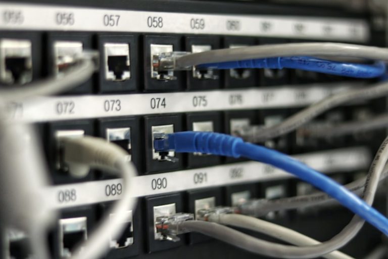
- Layer 1 – Physical: This is the actual transmission medium—Cat6a copper cable carrying 10GBASE-T signals, single-mode fiber with 1000BASE-LX optics, or radio waves for Wi-Fi. Layer 1 problems manifest as link down, CRC errors, or signal degradation. Troubleshooting tools include cable testers, OTDRs for fiber, and interface counters (input errors, runts, giants).
- Layer 2 – Data Link: Ethernet frames with source and destination MAC addresses operate here. Switches forward frames based on MAC address tables. Key protocols include ARP (mapping IP to MAC), STP (preventing loops), and LACP (link aggregation). VLAN tagging via 802.1Q also happens at this layer.
- Layer 3 – Network: IP addressing and routing—this is where routers, Layer 3 switches, and routing protocols (OSPF, BGP, EIGRP) live. ICMP (ping, traceroute) operates at this layer. Problems at Layer 3 manifest as unreachable destinations, routing loops, or incorrect subnet masks.
- Layer 4 – Transport: TCP provides reliable, connection-oriented delivery with sequencing, acknowledgments, and flow control. UDP offers connectionless, low-latency delivery. Port numbers (0-65535) identify specific application endpoints. Firewalls and load balancers make most of their decisions at this layer.
- Layer 5 – Session: Manages dialog control between applications—establishing, maintaining, and terminating sessions. NetBIOS, RPC, and SOCKS proxies operate at this layer. In practice, session management is often handled at the application layer in modern protocols.
- Layer 6 – Presentation: Handles data format translation, encryption, and compression. SSL/TLS encryption, JPEG compression, ASCII/EBCDIC conversion, and MIME encoding all happen here. This is why HTTPS traffic appears as encrypted blobs at higher layers.
- Layer 7 – Application: The interface between the network and user applications. HTTP, SMTP, DNS, FTP, SSH, and SNMP all operate at this layer. Application-layer firewalls (WAFs) inspect traffic at this level to detect SQL injection, XSS, and other application attacks.
Troubleshooting Methodologies
The bottom-up approach starts at Layer 1 and works upward—check cables, verify link status, confirm MAC learning, test IP connectivity, validate TCP sessions, and then inspect application behavior. This is the most thorough method. The top-down approach starts at the application layer and works downward, useful when a specific application is failing but general connectivity works. The divide-and-conquer approach tests Layer 3 (ping) first—if it works, the problem is likely at higher layers; if it fails, focus on lower layers.